The functional block diagram of a stabilizer utilizing electromechanical transformer tap changing with relays is shown in figure 1. This is a relay type voltage stabilizer circuit diagram.

Voltage Stabilizer Working And Its Importance

Electricfield Products

Circuit Diagram Of The 5 Kva Microcontroller Based Automatic
High quality single phase 5kva stabilizer circuit diagram home power stabilizer ac 220 volt stabilizer find complete details about high quality single phase 5kva stabilizer circuit diagram home power stabilizer ac 220 volt stabilizerac 220 volt stabilizer5kva stabilizer circuit diagramsingle phase home power stabilizer from voltage regulatorsstabilizers supplier or manufacturer zhejiang.
5 kva stabilizer circuit diagram. A wide variety of 5kva stabilizer circuit diagram options are available to you such as single phase three phase. About 100 of these are voltage regulatorsstabilizers. Functional block diagram of an ac.
The suggested circuit of a basic 5 kva to 10 kva automatic voltage stabilizer circuit is simple to recognize. Stabilizer using electromechanical transformer tap changing with relays. Working of stabilizer circuit.
The next page covers the circuit and the construction details of this automatic voltage stabilizer circuit. Circuit design of stabilizer is quite easy and compact. It makes use of relays connected in series with autotransformer taps.
Solid state ssr voltage stabilizer circuit diagram. With the help of automatic voltage stabilizer circuit we are able to keep constant voltage at 230v when voltage goes low as 170v and high as 250v automatically. Circuit diagram of the 5 kva microcontroller based automatic voltage stabilizer.
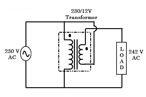
Full circuit diagram of the proposed a simple 5 kva to 10 kva automatic voltage stabilizer circuit at 220 volts 120 volts. A 12v step down transformer is used to drive the stabilizer circuit and the same transformer is used to analyze the input line voltage. Interlink all of them as per the circuit schematic.
The presets p1 to p7 can be modified as per the needed tripping points which is able to correspond to the output ssr switching and the successive transformer tap. All the opamps are organized in regular voltage comparator modes. Finally connect the primary and the secondary wires of the transformer to the relay contacts as shown in the diagram.
The function of the autotransformer is to produce the required output voltage with the help of the control unit. Ssr 10kva230volts output 5 to 32 volts dc input. The project posted here is of called automatic voltage stabilizer circuit which solves almost all problem faced in normal available stabilizer efficiently.
Implementation of a microcontroller based 5 kva automatic voltage stabilizer g. Manual stabilizer transformer winding data 5 kva autocut circuit stabilizer from s m e hi am sankat mochan welcome to my channel sme thanks for watching fr.

Automatic Voltage Stabilizer Circuit For Tv Sets And
Circuit Diagram Of The 5 Kva Microcontroller Based Automatic
Voltage Stabilizer Electronics Post

Comments
Post a Comment